We want to implement on a Nexys 3 board a robot toy module which simulates sleeping. Its interface is :
The toy should work as follows :
the state of the toy is reassessed every 2 seconds to the clock rate of H.
when the toy is awake, his eyes are opened and he laughs.
when the toy is in a state of light sleep, his eyes are closed and he growls.
when the toy is in a state of deep sleep, his eyes are closed and he snores.
when the toy is in distress, he cries and his eyes are opened.
the toy into waking state remains on waking state with the light on , even if there is noise.
for puting the toy in a state of light sleep, it is from the waking state, then turn off the light and in the absence of noise. Turning off the light with noise places the toy in distress.
when the toy is in distress state, he returned to the waking state to the next clock edge where the light is on, with some noise or not. Otherwise it remains in distress.
when the toy is in a state of light sleep, it goes into deep sleep if the light continues to be extinguished without noise. Any other manipulation brings the toy in distress state.
the toy remains in a state of deep sleep if the light is off and there is no noise.
when the toy is in a state of deep sleep and the light comes on in the absence of noise, the toy goes to the waking state. Any other manipulation brings the toy in distress.
We first design the state graph of the toy which will be Moore type. After having got the corresponding module, we will implement it in SHDL (Simple Hardware Description Language) as the MDLE tool developed by Jean-Christophe Buisson in the IT department of ENSEEIHT.
The inputs are noted in the order light - noise (L - B) and the outputs eyes - voice(s[2] - s[1] - s[0]).
According to the specifications above, the toy robot has four possible states :
awake (opened eyes and he laughts) ; output = 101 ; denoted AW
light sleeping (closed eyes and he growls) ; output = 010; denoted LS
deep sleeping (closed eyes and he snores) ; output = 000 ; denoted DS
distress (opened eyes and he cries) ; output = 111 ; denoted DI
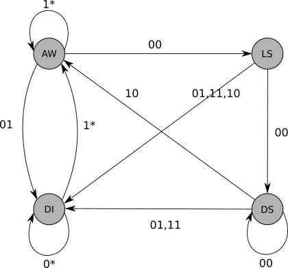
We deduce the following Moore State graph :
Figure : Moore State Graph of module
Here is the transition table that results :
inputs
state before
state after
00
101
010
01
101
111
10
101
101
11
101
101
00
111
111
01
111
111
10
111
101
11
111
101
00
010
000
01
010
111
10
010
111
11
010
111
00
000
000
01
000
111
10
000
101
11
000
111
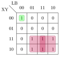
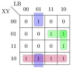
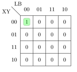
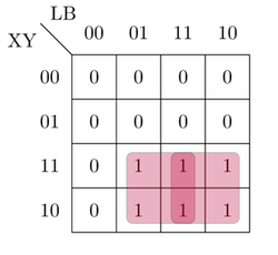
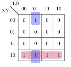
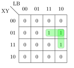
We calculate in two ways the relationship between outputs and inputs, the first method with 2 T flip-flops and the second with 2 JK flip-flops. With the heuristic rules whose goal is to minimize the number of bits that change (states or outputs) in the states changing, we make the following assignment :
The MDLE tool allows to simulate the operation of combinational and sequential circuits. It uses the language SHDL (Simple Hardware Description Language). In order to be teaching, his writing is very simple and enables the design of modules in a more condensed form that others standard hardware description languages like VHDL. For more information about the syntax, see here.
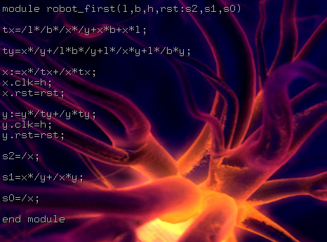
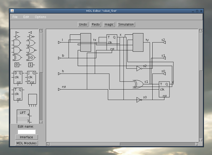
Here is the source robot_first.mdl corresponding to the module designed with 2 T flip-flops :
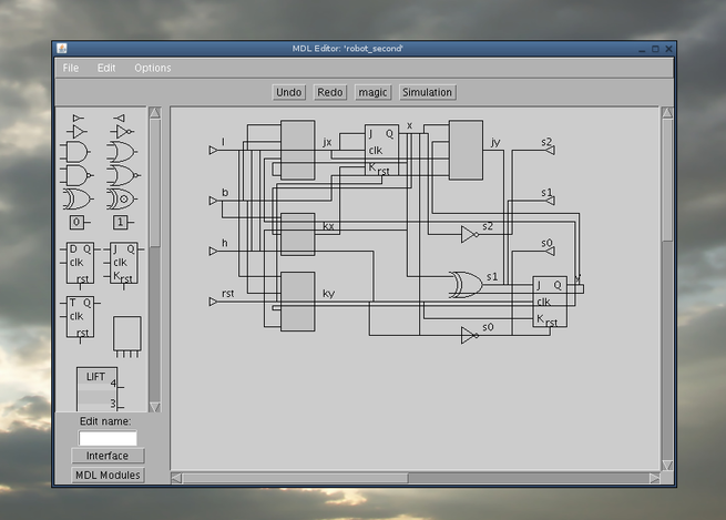
We can load the design with the graphical editor, like this :
With the MDLE simulator, we can browse the Moore graph as a function of time and inputs. This is illustrated on the following video :
We will initially implement hardware design that we have made above. The software Xilinx ISE can do this by generating a binary file (.bit) which can then be transferred from the PC to the FPGA board. After this first implementation, we will create a GUI to interact in real time with the card.
ISE allows to synthesize the sequential circuit module of our robot toy. To describe the design, ISE requires a hardware description file written in VHDL (rather used in Europe) or Verilog (rather used in United States). We will choose VHDL because we have a tool to convert a SHDL source into a VHDL source. This tool is called SHDL2VHDL Converter and can be downloaded here : shdl2vhdl2.1.4.jar .
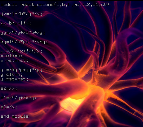
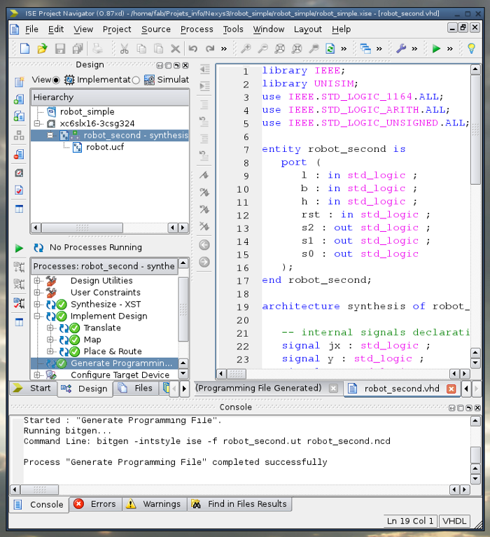
Use now the SHDL source robot_second.mdl (corresponding to the design in paragraph 2.4) and convert it into VHDL with the SHDL2VHDL tool, then we get the file robot_second.vhd :
library IEEE; library UNISIM; use IEEE.STD_LOGIC_1164.ALL; use IEEE.STD_LOGIC_ARITH.ALL; use IEEE.STD_LOGIC_UNSIGNED.ALL;
entity robot_second is port(
l :instd_logic;
b :instd_logic;
h :instd_logic;
rst :instd_logic;
s2 :outstd_logic;
s1 :outstd_logic;
s0 :outstd_logic ); end robot_second;
architecture synthesis of robot_second is
-- internal signals declarations signal jx :std_logic; signal y :std_logic; signal x :std_logic; signal kx :std_logic; signal jy :std_logic; signal ky :std_logic;
begin
-- concurrent statements
jx <=(not l)and(not b)and(not y)and(not x);
kx <=(b and x)or(l and x);
jy <=(x and(not y))or((not l)and b and(not y));
ky <=(l and(not b)and y)or(l and(not x)and y);
s2 <=not x ;
s1 <=(x and(not y))or((not x)and y);
s0 <=not x ;
-- sequential statements process(h, rst)begin if rst ='1'then
x <='0'; elsif h'eventand h ='1'then
x <=((not kx)and x)or(jx and(not x)); endif; endprocess; process(h, rst)begin if rst ='1'then
y <='0'; elsif h'eventand h ='1'then
y <=((not ky)and y)or(jy and(not y)); endif; endprocess;
end synthesis;
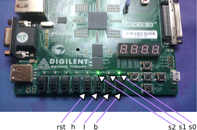
Into ISE project, we need a file to make the connection between the signals from VHDL design and I/O connectors of the FPGA board. This file is called "User Constraints File" (UCF). We choose the switches SW3, SW2, SW1 and SW0 for respectively entries reset (RST), clock (h), light (l) and noise (b) . For output, we use the LEDs LD2, LD1 and LD0 respectively for outputs s2 (eyes), and (s1, s0) (voice) . So we have the following file robot.ucf :
# Inputs
NET "l" LOC = "T9";
NET "b" LOC = "T10";
NET "h" LOC = "V9";
NET "rst" LOC = "M8";
# Outputs
NET "s0" LOC = "U16";
NET "s1" LOC = "V16";
NET "s2" LOC = "U15";
We add "robot_second.vhd" and "robot.ucf" in the ISE project, and generate the .bit file. Here is a screenshot :
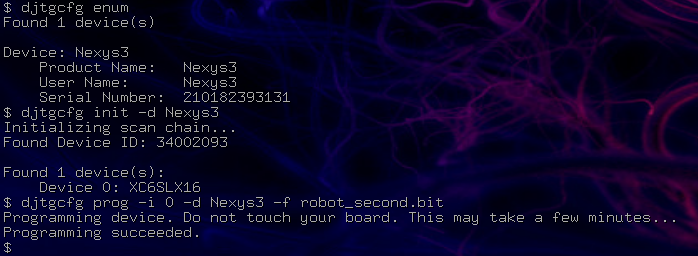
For loading under Linux terminal the the "robot_second.bit" generated file, there are 3 commands to do :
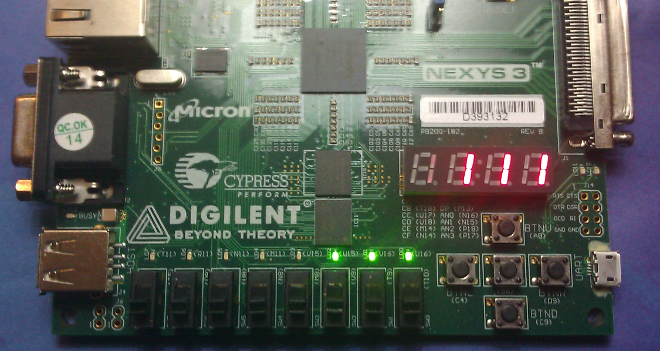
Here is a picture of the board with the inputs (rst, h, l, b) and the initial ouputs (Awake state : 101) :
In the design, we can add 3 seven-segment displays ; that's we show in this source robotseg.vhd :
library IEEE; library UNISIM; use IEEE.STD_LOGIC_1164.ALL; use IEEE.STD_LOGIC_ARITH.ALL; use IEEE.STD_LOGIC_UNSIGNED.ALL;
entity robotseg is port(
l :instd_logic;
b :instd_logic;
h :instd_logic;
h1 :instd_logic;
rst :instd_logic;
an :inoutstd_logic_vector(0to3);
ss :outstd_logic_vector(0to2);
ssg :outstd_logic_vector(0to7) )b; end robotseg;
architecture synthesis of robotseg is
-- clock
signal CTR :std_logic_vector(12downto0);
-- buffer signals declarations
signal ss_int :std_logic_vector(0to2);
-- internal signals declarations
signal jx :std_logic; signal y :std_logic; signal kx :std_logic; signal x :std_logic; signal jy :std_logic; signal ky :std_logic;
begin
-- concurrent statements
jx <=(not l)and(not b)and(not y)and(not x);
kx <=(b and x)or(l and x);
jy <=(x and(not y))or((not l)and b and(not y));
ky <=(l and(not b)and y)or(l and(not x)and y);
ss_int(2)<=not x ;
ss_int(1)<=(x and(not y))or((not x)and y);
ss_int(0)<=not x ;
We are going to create a graphical user interface interacting in real time with the Nexys 3 board. We will use low-level functions of the dpcutil library in order to send and receive signals from the board. Firstly, we need to integrate into the previous design the USB communication. I/O data are stored in the register at the adress 10 ("regEppAdr=1010" in the dpimref.vhdl). The constraints file is pins.ucf. After building the .bit under ISE and transfering it on the board, we use the following GTK/OpenCV GUI :